What is a Requirement Diagram?
Smartpedia: A requirement diagram visualises requirements of a system, relations between requirements and relations to other model elements.
Requirement diagram – the visualisation of requirements for a system
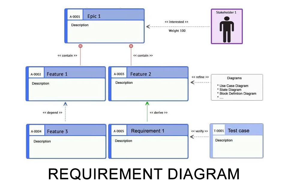
A requirement diagram visualises requirements or parts of requirements placed on a system or software. It originates from the System Modeling Language (SysML) of the Object Management Group (OMG) and, compared to a pure textual representation of requirements, promotes an understanding of interrelationships. This understanding is deepened by the use of different relations – i.e. relationships, types and directions of the relationships.
The requirement diagram provides a visual overview of requirements and ensures greater traceability in development.
Origin of the Requirement Diagram
In 2001, the OMG in cooperation with the International Council on Systems Engineering (INCOSE) published a Request for Proposal with the requirement to develop a notation for describing systems based on the Unified Modeling Language (UML). The result was the so-called Systems Modeling Language (SysML), which was published with version 1.0 in 2007. In December 2017, the OMG published a Request for Proposal for the Systems Modeling Language Version 2, RFP for SysML v2 for short.
In the current version, the SysML defines structure diagrams, behavior diagrams and, as an independent diagram, the requirement diagram. Structure diagrams are the block definition diagram, the package diagram and the internal block diagram. The behavior of a system can be described by activity, state, sequence, and use case diagrams. While the package, dtate, sequence, and use case diagrams correspond to the UML 2 notation, the block definition diagram (as a variant of the UML class diagram), the activity diagram, and the internal block diagram have been modified. The assurance diagram and the requirement diagram have been republished.
The importance of requirements
Developing a software or system without requirements is impossible. A system should do something and that something arises from the realisation of requirements. Stakeholders pursue goals and they expect the developed solution to help them achieve their goals. However, goals are too rough to derive specific characteristics of a system from them – requirements help here. Requirements concretise goals. Even when using abstractions such as Epics and Features, the message is the same: Requirements are essential for the development of a solution, especially since implementation activities, risk assessment or architectural design are based on them. Two points are important: Requirements for a new system must be complete, consistent and precise. Ideally, requirements can be determined using a defined process. And dependencies and relationships must be as clear as possible before implementation – requirement diagrams help here.
The ideal number of elements in the Requirement Diagram
Tests have shown that short sentences are easier to understand than long sentences. The best text comprehension is achieved with sentences of 9 words. So should diagrams also contain about 9 elements? If you develop systems, you might ask yourself such a question. But there is no formula or test to determine the ideal number of model elements per diagram, nor is there an optimal number of diagrams to describe systems.
It is important that you use a requirement diagram to improve your understanding and make it easy for you to see what information is in the diagram or what is missing. If you develop the requirement diagram as part of a team or explain it to the team after it has been created, common understanding will be fostered and that is what modeling requirement diagrams is all about.
Relationships in the Requirement Diagram
The following relationship types can be used in requirement diagrams:
- The Derive Requirement Relationship in order to derive requirements from existing requirements.
- The Refine Relationship in order to describe a requirement in detail using additional diagrams such as a use case diagram.
- The Namespace Containment Relationship expresses that a requirement is contained in another requirement.
- The Satisfy Relationship indicates that a requirement is met by a design element.
- The Dependency Relationship expresses the content dependency of a requirement on another requirement.
- The Verify Relationship in order to verify a requirement by a test case.
- The Copy Relationship identifies the relationship between a requirement copy and its original.
- The Trace Relationship can be used to track relationships, for example, to link functional to non-functional requirements.
Some tool vendors offer the use of additional relationships between elements in the requirement diagram:
- The Interest Relationship is used when, for example, a stakeholder or persona is interested in a requirement.
- The Needs Relationship is used when a stakeholder or persona needs a solution to a requirement.
- The Note Relationship helps to display additional explanations or notes.
Advantages of working with Requirement diagrams
Working with requirement diagrams offers several advantages:
- They are easy to create and understand. Communication about concrete information is made easier and correlations are identified more easily.
- Missing aspects can be easily identified to help identify additional requirements.
- The different types of relationships facilitate traceability and promote understanding.
- They provide for order and thus for a higher quality when working with requirements.
- Compared to the pure textual description of requirements, they facilitate detailed work on concrete aspects that are important for development.
The increasing number of requirements is often accompanied by the concern of losing track of the desired system. Requirement diagrams could help here. Ideally, however, you should not simply draw a requirement diagram on a whiteboard or with a graphics program, but create it with a professional database-supported solution. So you can use your findings directly for the collection of new requirements or the modeling of relationships and do not have to document your results afterwards or transfer them to the tool of your choice. So it doesn’t matter how many diagrams you create – you simply create diagrams whenever you want to understand relationships or visualise them. You will gain clarity and increase your common understanding.
Download the Requirement Diagram Guide for free now.
Everything important about Requirement Diagrams at a glance.
- What is the meaning of requirements?
- What is a requirement diagram and where does it originate?
- Which relations can be depicted in a requirement diagram?
- What is the ideal number of diagram elements?
- What advantages do requirement diagrams offer?
Knowledge on 5 pages to take away.
Impulse to discuss:
Are requirements diagrams also useful in agile projects?
Notes:
If you like the article or would like to discuss it, please feel free to share it in your network. And if you have any comments, please do not hesitate to send us a message.
Here you can find additional information from our t2informatik Blog:


