What is an Use Case Diagram?
Table of Contents: Definition – Elements – Releationships – Questions from the field – Download – Notes
Use case diagram definition
A use case diagram is a graphical representation of use cases including their relationships to the environment and to other use cases. It thus describes in a high abstraction which functions and services a system provides for a user.
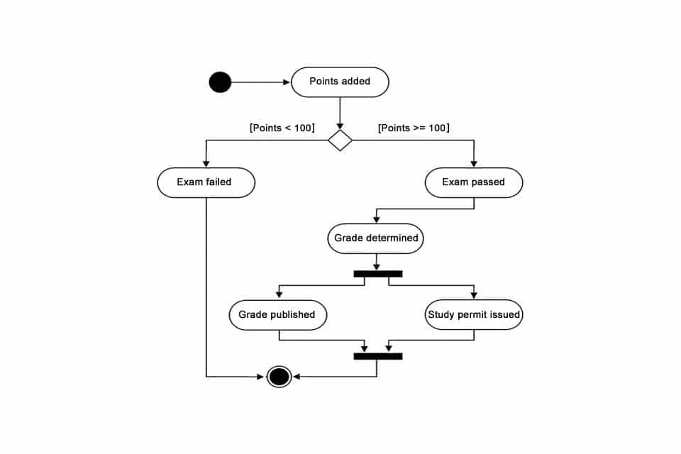
With a use case diagram neither the processes of the system are described nor the sequence of the functions or services is shown.Other behavioural diagrams in UML, such as activity diagrams, communication diagrams, state machine diagrams or sequence diagrams, can be used to define the sequence of operations. A use case diagram merely visualises the relationships between a set of use cases and the actors involved. It is therefore very well suited for requirements analysis, i.e. for determining or refining requirements.
Elements in the use case diagram
The following elements are visualised in a use case diagram:
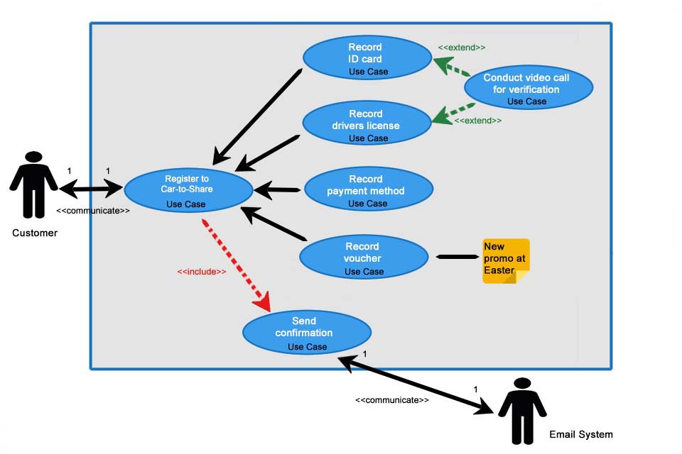
- The system itself is not a logical model element, but delimits the context. This system context is represented by a frame in the diagram in which the system provides its functions and services.
- The actor is outside the system. He is drawn as a stick figure and can be a concrete person or an abstract element such as a sensor. The refinement of a href=”/en/smartpedia/actor/” title=”What is an actor?”>actors can take place via UML profile. If an actor is defined, it must always be connected to at least one use case. If several actors are involved, this is expressed by the multiplicity. Without further specification, this is 1 by default.
- An use case is usually displayed as an ellipse, whereby its name can also be outside the ellipse. A diagram can contain several use cases. If a use case can only be executed by other use cases, it is referred to as abstract. Multiplicity can also be displayed for use cases; it provides information on how often the use case can be executed simultaneously.
- Relationships exist between actors and use cases and between use cases.
- Notes can be used to add information to increase understanding. They are represented by a rectangle, the upper right corner of which is folded. A stitched line connects the note with the element to be explained.
Relationships in the use case diagram
Actors and use cases are just as related to each other as use cases are to each other. Basically, four different relationships or relationship types can be used in a diagram:
- association,
- include,
- extend and
- generalisation.
Relationships are modeled with dashed or solid lines and arrows. The direction of the relationship should not be understood as a data flow; it describes, for example, which use case extends another.
Association relationship
When an actor communicates with a use case, this is referred to as a communication relationship or association. The direction of the line describes which part is active and which part is passive. If the arrow flows from the actor to the use case, the actor is active and triggers the use case. If the arrow flows from the use case to the actor, the use case is active and prompts the actor to participate.
Include relationship
The include relationship links a primary or base use case with one or more secondary use cases. It is useful to model an include relationship if parts of use cases occur in several use cases. This avoids redundant descriptions. In practice, secondary use cases are often marked with the stereotype “secondary”, even if this is not provided for in UML. There are five aspects to include relationships:
- An included use case is ALWAYS executed when the included use case is executed. However, the time of execution cannot be specified in the diagram; the specification is suitable for this.
- An included use case can also be executed separately.
- Primary and secondary use cases should be described at similar levels of abstraction. Detailing in included use cases should be avoided.
- Descriptions can be used as often as desired by include relationships.
- In contrast to generalisation, no properties are inherited.
The include relationship is represented in a use case diagram by a dashed arrow and the include caption. The arrow points to the included use case.
Extend relationship
If parts of an use case are only executed under defined conditions, it is advisable to apply the extend relationship. The extend relationship adds a function to the basis use case. Example: Each year you must declare your income using a tax return (basis use case) and from a defined income amount you must enclose documents (extension of the basis use case). The basic use case thus decides whether the extended use case – which does not necessarily have to involve an actor – is executed. Both cases can be executed separately. An extend relationship is shown by a dashed arrow labeled extend. The arrow always points to the basic use case.
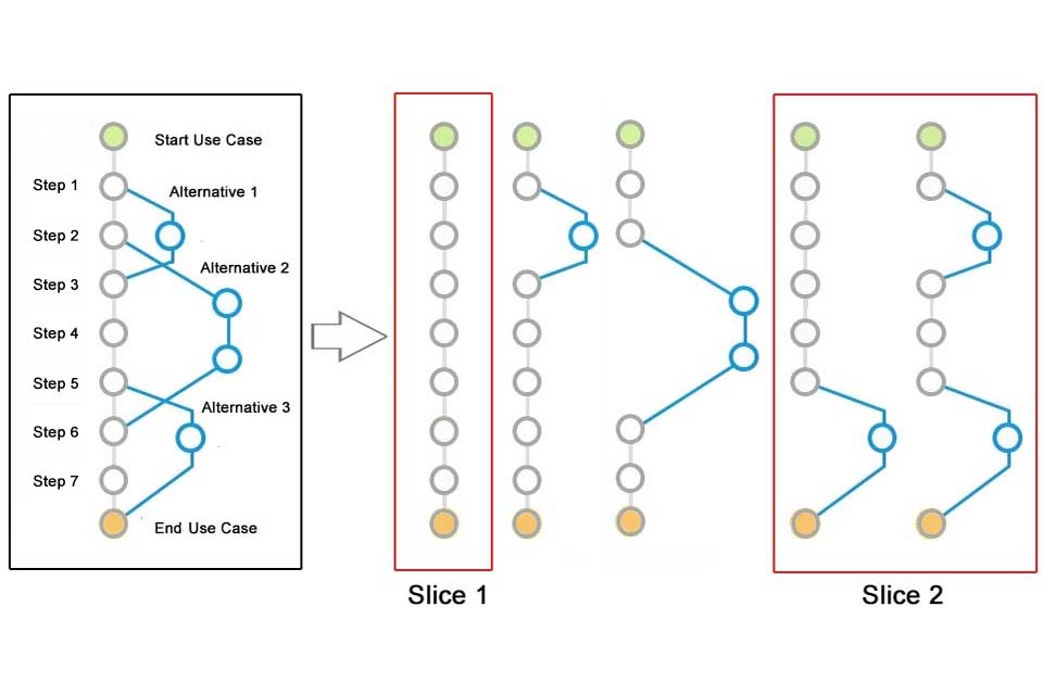
The extended use case can be described in detail by so-called extension points. This allows you to document the event or time at which the original behavior is extended. Conditions can also be defined; if a condition occurs, the extension is executed. A use case can have any number of extension points.
Generalisation
There are two forms of generalisation in a utility diagram:
- between actors and
- between applications.
Imagine there are two players: a fruit seller and a salad seller. Since both have characteristics that they share, a general actor can be derived from them: a seller. The advantage of such generalisation lies in the general and abstract description of the new actor seller and in the combination of the use cases with other use cases, which only apply to the specialists (fruit or salad sellers). This is often referred to as specialisation. Just like actors, use cases can also be generalised. In the use case diagram, generalisation always points in the direction of the more general element, hence the term generalisation. This type of connection is also called a sort of relationship, since the more specific use cases and actors “inherit” everything from the more general element.
Questions from the field
Here you will find some questions and answers from the field:
What are application areas of Use Case Diagrams?
Use Case Diagrams are often used in the context of a requirements analysis or in the process of requirements engineering. They can be used to record requirements for a system – consisting of software and/or hardware. They are well suited for communication and analysis of system behavior because they can be used to define the functionality of the system from the user’s point of view. Implementation details, such as the system architecture or the programming language to be used, are not yet important in this phase and can be discussed in subsequent steps.
The system analysis determines what a system should achieve from the user’s point of view. The individual cases are recorded and visualised as use cases. A Use Case Diagram thus represents a sketch of the system, which indicates the purpose of the planned system including boundaries and interfaces. All modeled elements are documented in a specification, ideally also with alternative procedures and the behavior description in case of an error.
What rules should be observed when designing use case diagrams?
When designing Use Case Diagrams, it is advisable to observe some rules:
- Even if actors are drawn in outside the system, they should never be displayed without a relationship to a use case. Isolated use cases should also be avoided.
- Crossings between relationships should be avoided.
- A Use Case Diagram should not include too many use cases, otherwise the display will quickly become confusing. Here it is recommended to distribute the contents over several diagrams.
When does it make sense to distribute use cases across several use case diagrams?
Use Case Diagrams provide a good view of a system. In them, companies can better put themselves in the position of their users and find solutions for these users by defining requirements and, as a result, test cases. The identification of topics and content is the first challenge for companies. The more employees are involved and the more comprehensive a system is, the more complex this step becomes.
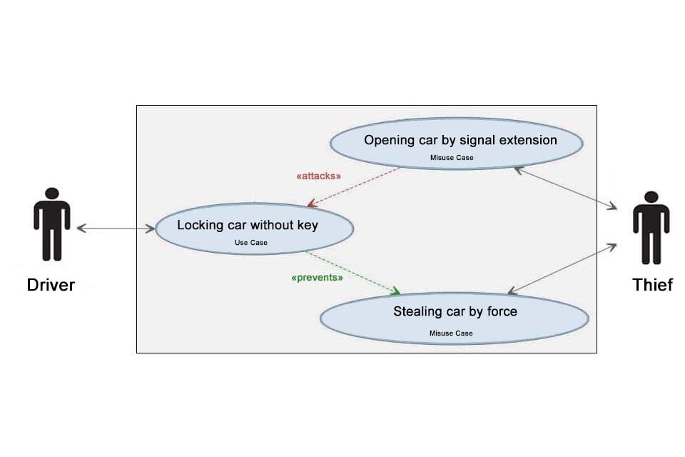
If an Use Case Diagram becomes confusing due to a large number of use cases, it is advisable to distribute use cases across different diagrams. But is another form of presentation the solution to the problem, or is the system as such too extensive to divide the system into subsystems? Such a decision is not easy to make. Working with use cases, diagrams, use case 2.0 and misuse cases offers a comprehensive concept to understand systems not only in detail but as a whole. Companies “only” need to apply the concepts consistently and appropriately to the organisation.
What advantages do use case diagrams offer?
Use Case Diagrams display use cases of one or more actors and relationships between the use cases. The application offers a number of advantages:
- Systems are consistently viewed and described from the user’s point of view, which promotes understanding and helps communication between users, system analysts and developers.
- They offer an additional perspective on the system and on relationships between individual use cases; concrete requirements and test cases can be derived from this. The refinement of existing requirements is also supported.
- They help to structure a system to be developed and to define the system boundaries. This is an essential factor for a successful development.
Download the Use Case Whitepaper for free now.
Everything important about Use Cases at a glance.
- What are use cases and how are they created?
- Which components do use case diagrams have?
- How does Use Case 2.0 work and what are misuse cases?
- What are challenges and what useful tips exist?
Knowledge on 14 pages to take away.
If you like the article or would like to discuss it, please feel free to share it in your network. And if you have any comments, please do not hesitate to send us a message.
Here you can download an use case template for free.
Here you will find additional information from our Smartpedia section:
