What is the UML?
Smartpedia: The UML (Unified Modelling Language) is a standardised, graphical modelling language for the specification, documentation and visualisation of systems.
UML definition
The Unified Modelling Language – usually abbreviated as UML – is a graphical modelling language for the specification, documentation and visualisation of software systems. It offers various diagram types for the analysis of structures, the determination of object interactions and the behavioural design of systems.
The idea of the Unified Modeling Language goes back to Grady Booch, James Rumbaugh and Ivar Jacobson, who developed various object-oriented methods specialised in defined application areas into a consolidated approach. The approach of the “three amigos”, who worked for the Rational Rose company, quickly became a quasi-standard. The Object Management Group (OMG) took up the approach and published UML version 1.1 in 1997. The current UML version is 2.5.1, published by the OMG in December 2017.¹ Version 2.4.1 is standardised by ISO (ISO/EEC 19505).
UML diagram types and diagrams
UML 2.5 includes a total of 14 diagrams, which are divided into three groups or diagram types:
- structure diagrams,
- behavioural diagrams and
- interaction diagrams.
Structure diagrams are all diagrams that model a static component of a system, in which the data change but not the structures of the elements and their relationships to each other. A behaviour diagram visualises individual aspects of a system, the sequence of processes and their changes at runtime. And interaction diagrams visualise the interactive behaviour of a system and thus the flow of information in a system.
The variety of diagrams enables practical use across all phases of a development; UML diagrams can be used, for example, for requirements documentation, the design of a software architecture, technical documentation or, with appropriate tool support, for the implementation of systems.
The following structure diagrams exist:
- class diagram,
- object diagram,
- composition structure diagram,
- component diagram,
- distribution diagram and
- package diagram.
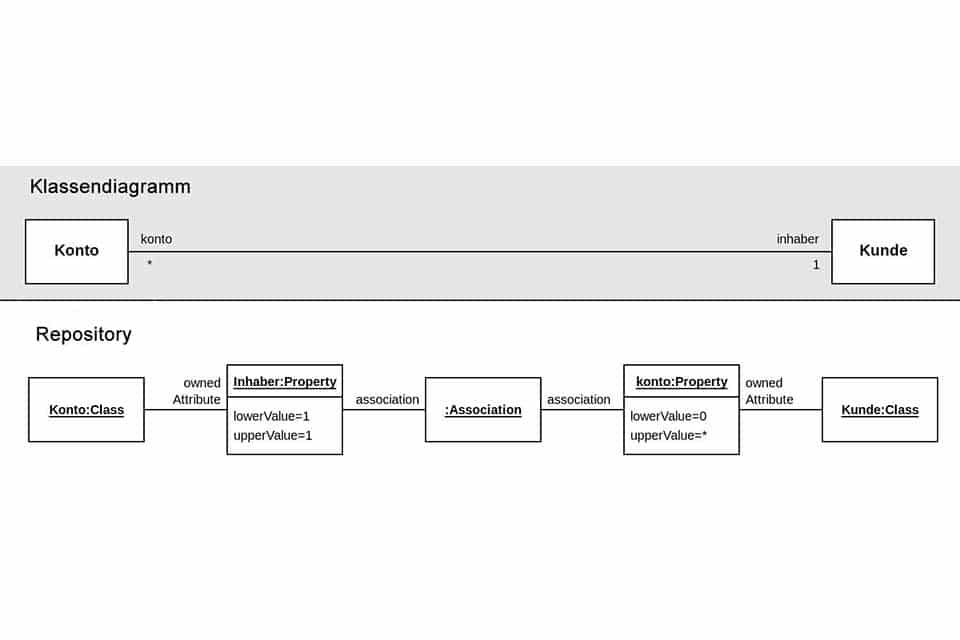
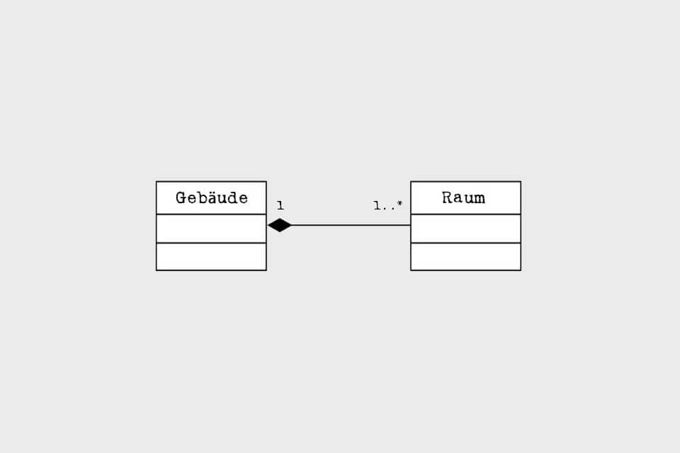
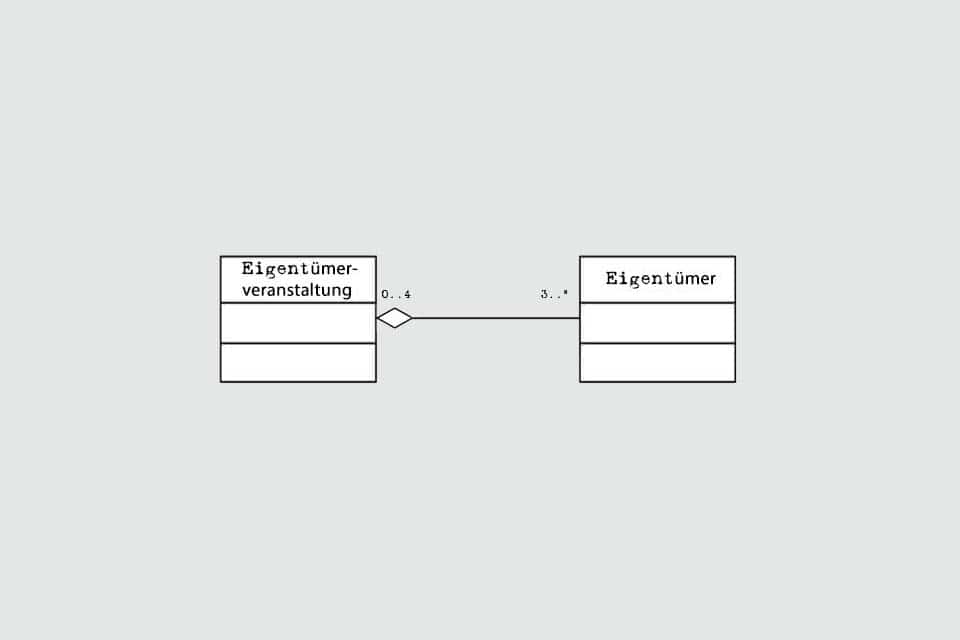
In class diagrams, classes and the relationships between classes are modelled as association, aggregation, composition or generalisation. An object diagram describes a concrete instance of a class diagram at a defined point in time. A composition structure diagram shows the internal structure of a classifier and visualises the configuration of the elements that together determine the behaviour of the classifier. A component diagram depicts the structure and relationship between different components of a system. The distribution diagram models the physical distribution of artefacts to nodes (hardware and software). And the package diagram is used to represent a group of model elements – the packages – and the dependencies between the packages of a model.
The following behaviour diagrams exist:
A use case diagram visualises the behaviour of a system from the user’s point of view. It shows use cases with their relationships to other use cases and to other systems. Activity diagrams show the sequence of activities, processes in systems or business processes, and state machine diagrams – sometimes referred as state diagram – visualise a sequence of permitted states that an object can assume in its life cycle.
The following interaction diagrams exist:
- sequence diagram,
- communication diagram,
- timing diagram and
- interaction overview diagram.
A sequence diagram describes how objects and their instances exchange information in a certain order. The communication diagram – still called a collaboration diagram in earlier versions of UML – highlights selected messages that are used to sequence the communication between objects. A timing diagram shows objects interacting with each other during a defined period of time. And an interaction overview diagram links activities and processes to show permitted interactions between elements with decisions and information flows.
In addition, the Unified Modeling Language also knows a diagram for metamodelling:
- profile diagram.
The profile diagram is used at the metamodel level to visualise user-defined stereotypes, property values and constraints.
Advantages and disadvantages of the Unified Modeling Language
The use of the Unified Modeling Language offers some advantages, but may also have some disadvantages in practice. Here are some advantages:
- The modelling language is versatile and flexible. It is suitable, for example, for the specification, visualisation or documentation of systems or software. And it can be used independently of sectors or industries and in all phases of a development.
- Each diagram offers suitable elements with which specific information and contexts can be worked out and presented. Through specialisation, each diagram already offers a benefit or added value in itself.
- The use of the modelling language ideally leads to a better understanding of the system to be developed or documented and can contribute to the reduction of possible costs, e.g. during the implementation or maintenance phase.
- Ideally, the modelling language also promotes the cooperation of all users such as software architects and software developers, business analysts, project managers or product managers.
- The Unified Modelling Language not only provides a graphical view of a system, but also includes a format for exchanging models or diagrams between different tools. This also increases flexibility in the application.
- And last but not least, various tools support the transformation of domain-oriented UML models into technical models with subsequent code generation; so-called model-driven development.
The following criticism² is voiced, among others:
- The documentation of UML 2.5 is very extensive with 794 pages. Even if earlier versions were even more extensive, that is a lot of pages with a lot of information. In addition, opinions differ as to whether the documentation is easy to read and understand.
- There is no formula for determining a sensible number of diagrams to describe and visualise the interrelationships of a system or software development. And there is also no ideal number of diagram elements per diagram; as the size of a diagram increases, clarity and readability are often lost. For the person who creates a diagram, it is probably easy to understand interrelationships. However, if you read an extensive diagram for the first time, it can easily happen that you cannot grasp all the information.
- Even though the Unified Modeling Language can be used in numerous areas, it is mainly used for documentation and rather rarely for the development of software or systems. As a result, diagrams are produced without productive value for development.
- In practice, diagrams often become outdated because they are not maintained appropriately when new information or enhancements are made. Furthermore, diagrams can be contradictory if they are “merely drawn” and not created with database-based tools.
There are a large number of providers of UML software. Depending on your perspective, this can be an advantage or a disadvantage. On the one hand, the large quantity makes it difficult to select software that fits the situation and the company; on the other hand, it also makes it possible for less experienced employees to use the modelling language, since professional software pays attention to adherence to the notation, automatically versions intermediate states or facilitates the reuse of individual elements.
Some publications mention that entire systems are rarely modelled. However, this is not an explicit disadvantage of the Unified Modelling Language per se, on the contrary: depending on the application scenario, the means of expression should selectively help to gain a common understanding. If this is achieved through individual models, this clearly speaks for the flexible use of the modelling language. The full use of all diagrams is not a goal in itself.
The fact that the Unified Modelling Language does not include a guide for developing systems or software, or even that it is a programming language, is neither an advantage nor a disadvantage.
UML tools
There is a whole range of UML tools that differ significantly from each other. There are free programmes for simply drawing diagrams and professional solutions that generate code based on diagrams. Some tools support selected diagram types, others offer full support for all diagrams. Some use a few symbols from the pool of individual diagrams, others are able to reuse defined elements in different diagrams. Some support reverse engineering or roundtrip engineering, others XMI support.³ Some tools are client-server applications, others run online in the browser and store data in a cloud. Some support the exchange of information between UML tools, and others offer customisable reporting. So if you are interested in a UML tool, you should know the scenario in which it will be used.
Here you can find a list of UML tools:
- BOUML
- Cacoo
- CaseComplete
- Chart Mage
- Concept Draw
- creately
- DotUML
- EdrawMax
- GitMind
- gliffy
- IBM Engineering Rhapsody
- IBM Rational Software Architect Designer
- JetUML
- Lucidchart
- modelio
- MS Visio
- PlantUML
- QM
- SinelaboreRT
- Software Ideas Modeler
- smartdraw
- StarUML
- System Architect
- TextUML
- UMLet
- UModel
- Umple
- USE
- Visual Paradigm
- WhiteStarUML
- xtUML
- yEd Graph Editor
- yuml
- ZenUML
Impulse to discuss
How important is it for the practice of modelling that new UML versions are published every few years?
Notes:
[1] Here you can find the official documentation of the OMG Unified Modeling Language Version 2.5.
[2] Here you can find further criticism in the form of 13 Reasons for UML’s descent into darkness.
[3] Quite a few tools allow saving and exporting UML models in XMI format. In practice, however, many of these tools have difficulty in correctly importing XMI files exported by tools from other manufacturers. It is therefore advisable to carry out an appropriate test.
If you like the article or would like to discuss it, please feel free to share it in your network. And if you have any comments, please do not hesitate to send us a message.
And here you will find additional information from our Smartpedia section:


