What is an Internal Block Diagram?
Smartpedia: The Internal Block Diagram shows the internal structure of a system module. It is a structure diagram of the SysML with origin in the composition structure diagram of the UML.
Internal Block Diagram – representation of the internal structure of a system module
The Internal Block Diagram (in short: ibd) is a diagram of the Systems Modeling Language (SysML). It is used to represent the internal structure of a system block. The internal block diagram has its origin in the composition structure diagram of the Unified Modeling Language (UML), which is used to describe the internal structures of classes. While the Composition Structure Diagram only describes the relationships of objects using parts, the Internal Block Diagram has been extended by the following functions:
- Representation of properties of a system block
- Notation of arbitrary nesting depths
- Information object flows between elements
The Internal Block Diagram is also called a Structure Diagram. It tries to create a better understanding for functions of the system and connections within the system by the graphic representation and is often easier to understand and comprehend than a purely textual description.
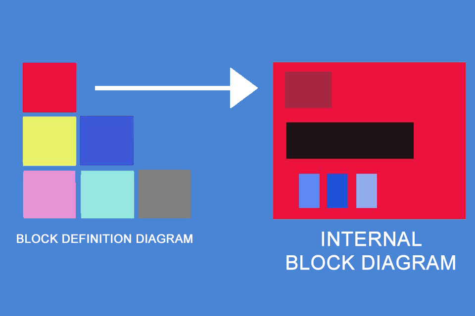
Interaction with Block Definition Diagram
Imagine a laptop as an example: It consists of a keyboard, a display, a motherboard and various interfaces, etc. This structure can easily be represented with a block definition diagram. But what is the structure like on the motherboard with its different elements and interfaces? Here the Internal Block Diagram is used. As the name suggests, it visualises the inside of a block. It uses the same means of expression – elements and relationships – as the block definition diagram.
Notes:
If you like the article or would like to discuss it, please feel free to share it in your network. And if you have any comments, please do not hesitate to send us a message.
Here you will find additional information from our Smartpedia section:


